The Best Tutorial On | Cylinder Head Of Marine Diesel Engine
Cylinder Head Marine Diesel Engine
Introduction
In this post on Cylinder head Marine Diesel Engine, we will discuss the complete details of cylinder heads, including- Cylinder head mountings, maintenance of mountings, Valve clearance adjustments.
Readers will get a clear insight about the Cylinder head for Marine Engines.
What is Cylinder Head?
The cylinder head is a metallic cast part that encloses the top part of the cylinder — the cylinder head mounts on the cylinder liner.
Marine Diesel Engine Cylinder Head Mountings (Cylinder Head Marine Diesel engine)
- Cylinder Head
- Inlet valve insert
- Exhaust Valve Insert
- Valve guide
- Bush for the fuel valve
- Valve operating mechanism
- Safety Valve
- Indicator valve

Generally, a cylinder head is of cast iron with a combined charge air receiver in one piece. The cylinder head bottom wall is thick with bore cooling provision.
The cylinder head has a central bore for the accommodation of the injection valve, two inlet and two exhaust valves with the cross-flow design, with a high flow coefficient and indicator valve for measuring the pressure inside the cylinder head and drawing the indicator diagrams.
Each valve has a spring and valve rotator. The yoke and rocker arm operates the valve opening and closing operation.
Seats for inlet and exhaust valves are fitted at the bottom of the cylinder heads. These seats are renewable when worn or damaged. Cooling water cools the exhaust valve seats.
The cylinder head also has a safety valve for the release of excessive pressure in high maximum pressure or pressure built-up during hydraulic lock inside the cylinder.
Location of the fuel injection valve is in the interchangeable sleeve in the centre of cylinder head. Comprehensive water cooling of the nozzle tip space makes it possible feasible to eliminate direct injection nozzle cooling.
Cylinder head assembly also includes an air starting valve for starting the engine.
Other assemblies are Rocker arms for actuating the inlet and exhaust valves.
A coaming on the cylinder head encloses the valve gears. Screw tightening of the top cover on coaming makes it possible for oil sealing of the complete chamber and complete cylinder head full-face covering. An inspection cover in the coaming facilitates the inspection of valve rotators.
Specific intake swirl is possible by 20 Degree turnings of the valve pattern. 4 nuts and studs tighten the cylinder head over cylinder liner with cylinder head gasket making it leak-free against the high combustion pressure inside the combustion chamber. Tightening of the nuts is by hydraulic jacks.
The cylinder head is part of the combustion space/chamber and needs overhauling /maintenance at regular intervals for high performance and reliable operation.
Check holes in the cylinder head indicate any leakage of mating surfaces between the cylinder head and cylinder liner.
Air Inlet and Exhaust Valves
The inlet and exhaust valve are of satellite coated seat, nickel-based alloy valve, and nemonic spindle.
Valve rotators provide a slight rotation to Valves. This valve rotation increases the life of the valve spindle.
Valve seats and valve guides are identical for inlet and exhaust valves. Valve seats and valve guides are interchangeable for inlet and exhaust valves.
The seat rings are of heat resistance steel, with direct hardening on the seat surface, and the water cools the seat ring for the assurance of low valve temperature.
Valve Rotator
Advantages of Valve Rotators
1. Carbon accumulation on the valve guide and seat.
2. Maintains uniform valve temperature
3. Prevents pitting due to hot spots.
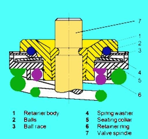
The valve rotator retainer body (1) has several pockets in the circumferential direction. As a result, the tangential action of coil spring forces the balls against the upper end of an inclined race.
The ball race (3) acts as a ball track in the opposition direction.
The inner rim of the retainer body holds the spring washer (4)to create the opposite springing action. Sealing collar (5) surrounds the spring washer by overlapping it.
Retaining ring (6) holds the assembled valve rotator while removing.
Dismantling Cylinder Head
1. Drain the cooling water from the engine.
2. Take out the rocker arm top cover.
3. Take out the side covers on both sides of the engine.
4. Remove the exhaust gas cover.
5. Remove the clamp of the cylinder head and exhaust gas receiver.
6. Remove the fuel oil high-pressure pipe.
7. Remove the clams for locking the freshwater connection between cylinder heads.
8. Remove the cooling oil inlet and outlet pipes.
9. Remove the rocker arm lubricating oil pipes
10. Remove the thermometer attachment branch.
11. Remove the exhaust pipe flanges
12. Remove the cylinder head nuts by using the hydraulic tool.
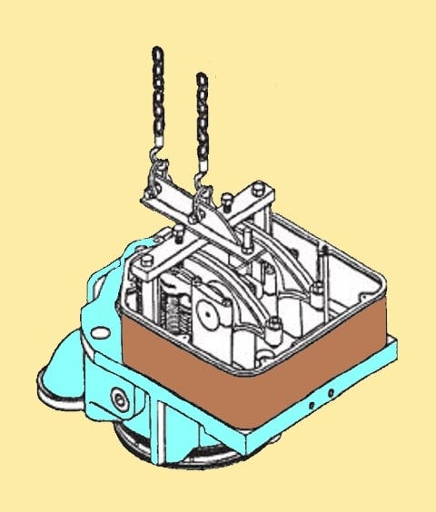
13. Fit the cylinder head lifting tool.
14. Fasten the hook to the lifting tool and lift the cylinder head away from the engine.
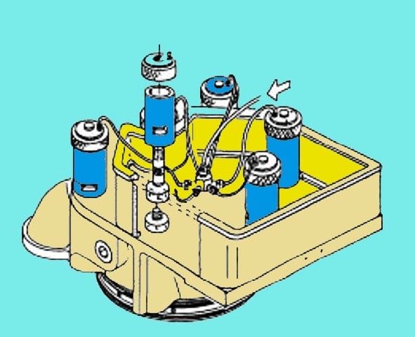
Inlet Valve, Exhaust valve, and valve guide Inspection
Exhaust and Inlet valve dismantling.

1. Mount the cylinder head on a working table
2. Install the valve spindle supporting device on the head
3. Remove the spring-loaded valve bridge.
4. Fit the tool as per the fig
5. Compress the spring by tightening the nut ( B).
6. Remove the valve cones/collets/valve locks.
7. Remove the valve rotators after removing the nut (B) and Traverse ©.
8. Remove the valve supporting device under the working table and draw out the valves.
Inspection of the valve and valve seats

9. If the pitting or burn-out of the valve lid and valve seat is minor, then lap the valve by hand lapping tool.
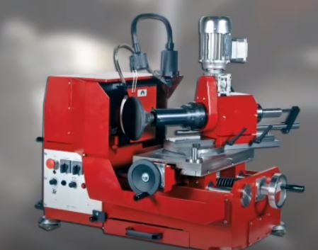
10. Grind the Valve seat on the grinding machine if the burn out/ pitting is more.
Inspection of Valve Guide
11. Inspect the valve guide for any pitting marks
12. Measure the valve guide bore.
Change the valve guide if the bore dimensions are found excessive than the prescribed limits.
Valve Seat ring and valve spindle re-conditioning
Valve Seat reconditioning
Carry out the reconditioning of the valve grinding machine.

Follow the following procedure
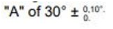
- Grind the seating surface with the following feed angle.
- Continue the grinding till the achievement of a clean and uniform surface.
- To obtain the best surface finish, carry out the grinding with feed-in opposite direction, i.e., inside to outward.
- Carry out the grinding till recess R is visible. Reject the seat if the recess R disappears.
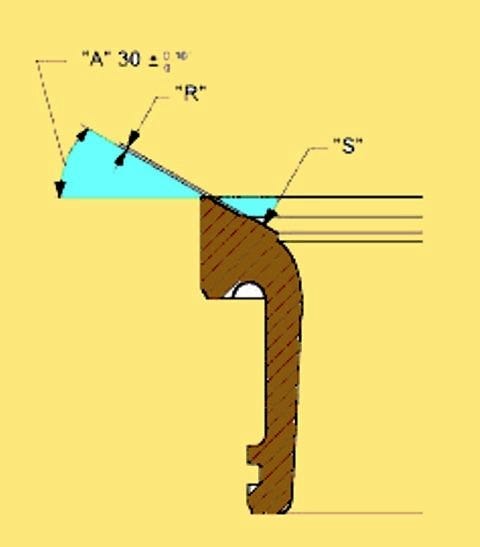
Valve Seat Surface checking after reconditioning
Check the contact of both the seating surface of the valve seat ring and valve spindle seat on completion of the grinding process of the valve seat ring.
- Apply the blue-compound thin layer on the valve spindle seating surface.
- Insert valve into the valve guide of the cylinder head.
- Rotate the valve to and fro by 1/3 turn with light pressure.
- Pull out the valve and inspect the contact pattern on the valve seat ring.
Observation:- The contact pattern/ mark should start from outer diameter towards inward radially, and the width of the contact area should be 2–3 mm continuously all over the circumference.
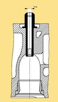
Valve Spindle re-conditioning
Carry out the reconditioning of valve spindles in the lathe machine and mount the special grinding machine in the tool post of the lathe machine.
Follow the following procedure for the above operation
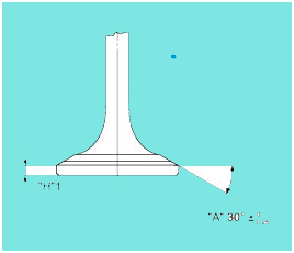

- Grind the seating surface with the feed angle illustrated in the above fig.
- Continue the grinding till the achievement of the clean and uniform surface of the valve seat lid.
- Check the height “H” on completion of the grinding process.
- The achieved H has to be as per the description of the below image.
Final check after the valve assembly in the cylinder head
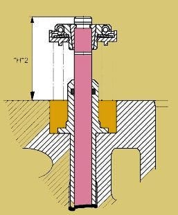
Check the Height “H”2 between the top end of the valve spindle and the upper edge of the cylinder head. The measurement should not exceed the value specified by the Equipment manufacturer.
Valve Guide Replacement (Cylinder head for Marine Engines)
It is mandatory to replace the valve guide if the clearance has increased more than the specified limits by the equipment manufacturer.
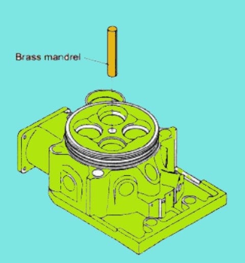
Valve Guide Removal Procedure
Blow out the valve guide from the bottom of the cylinder head using a special mandrel having shoulders. These shoulders fit at the collar of the valve guide.

- Clean the valve guide bore in the cylinder head after blowing out the valve guide. Inspect for any abnormal marks at the surface of the bore, which might restrict the proper fitment of the new valve guide.
- Cool the new valve guide to -70 deg C with dry ice/dry nitrogen.
- After inserting the new valve guide, tap slightly at collar with mandrel and hammer to ensure even seating at the cylinder head.
- Use a new ‘O’ ring in the valve guide before assembling the valve spindles.
Safety Valve Maintenance (Cylinder head for Marine Engines)
Clean the safety valve thoroughly during standstill and at Major maintenance of the engine. It is a bad practice to increase the spring tension to arrest the leak.
The opening pressure setting is marked/ stamped on the cap nut.
Safety valve dismantling procedure
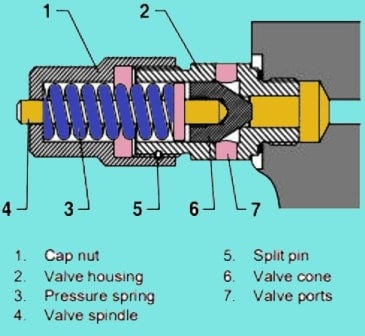
- Remove the safety valve from the cylinder head.
- Hold the valve in the table vice.
- Open the cap nut (1) by screwing it out.
- Take out the pressure spring (3)
- Remove the valve spindle (4).
- Remove the valve cone(6)
- Clean and inspect the valve carefully. Carry out the reconditioning of the valve if necessary.
Safety valve assembly procedure
- Smear the valve housing threads with copaslip or some other available substitute.
- Assemble the safety valve in the reverse sequence of operations 1 to7.
Safety Valve Test
Carry out the leak test and opening pressure test on completion of each overhaul.
- Connect the safety valve to the Fuel injection test pump with the help of a high-pressure fuel injection pipe.
- Keep venting the system by pumping till air-free bubble emerges out from port (7) in the valve body (2).
Safety Valve Leakage Test
- Slowly raise the pressure to 135 bars.
- Check the pressure drop for 01 minutes. Pressure shouldn’t fall below 135 bars within the above period.
- If the pressure is constant for 01 minutes, then continue raising the pressure to opening pressure.
- If the pressure falls below 135 in 01 minutes, scrap/ recondition the valve by lapping the procedure.
- Raise the pressure to opening pressure
- If the opening of the valve is correct at opening pressure, then finish with the test procedure.
- If the valve is not opening at the correct specified pressure, then carry out the re-adjustment of the valve.
Opening Pressure Adjustment
- Raise the pressure to opening pressure.
- Rotate the cap nut (1) to the correct opening pressure.
- Drill a hole to fix the safety pin (5).
Mounting back the safety valve
- Smear the threads on valve housing with copaslip.
- Fit back the safety valve in the cylinder head.
Indicating Valve
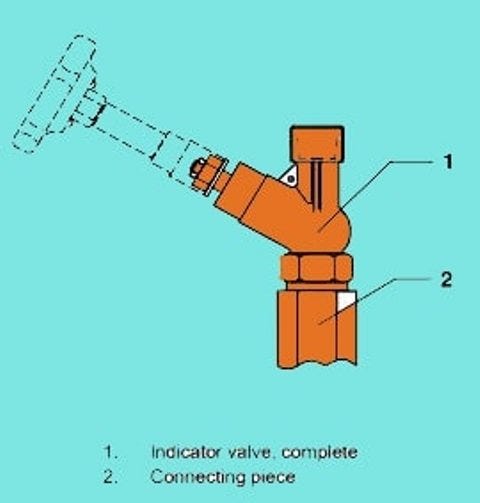
Uses of indicating valve are as under
- For blowing through the engine before starting
- For the measurement, Pmax and taking indicator diagrams.
- During engine crankshaft, easy shaft barring/Turning.
Indicating Valve Maintenance
In normal working conditions, the valve doesn’t require much maintenance except inspection during the cylinder head maintenance/ overhaul.
Indicating Valve Inspection
- Dismantle the indicating valve
- Visually inspect the condition of the valve cone and seat for any burning through.
- Replace the entire valve if the turning of the valve seat in the housing is persisting.
- Thoroughly clean and lubricate all parts of the valve before fitting back.
- Ensure that the valve spindle is in the fully open position during fitting back to prevent seat damage.
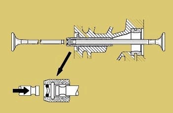
Injector Sleeve Replacement
Fuel Injector Sleeve removal
- Take out the snap ring using two screwdrivers
- Drive out the sleeve from the bore with the help of a hammer and brass mandrel.
Cylinder head bore for sleeve inspection and fitment of the sleeve.
- Clean and inspect the bore thoroughly for any burs or high surface, restricting the sleeve installation. Sooth the surface lightly with soft emery paper.
- Smear the sealing ring surface with lubricating oil/grease.
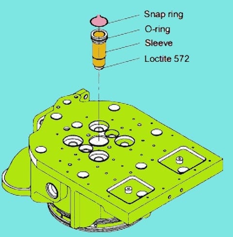
- Cool the sleeve in dry ice up to-15 Deg C.
- Insert a new sealing ring on the sleeve.
- Apply Loctite 572 at the sealing surface of the sleeve.
- Install the sleeve in the bore.
- Fit the snap/ lock ring.
Valve Seat Ring Replacement (Cylinder head for Marine Engines)
Extraction of Valve seat Ring
When reconditioning possibilities don’t exist due to the exceeding dimensions, reject the valve seat ring.
Extract the Valve seat ring with a special extractor tool consisting of the following tools.
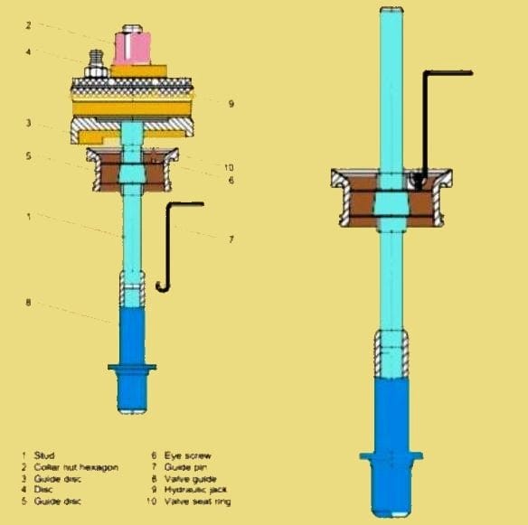
Valve Seat Extracting Method (Cylinder Head Marine Diesel Engines)
- Vertically place the guide disc (5) with the help of guide pin (7) through the valve set ring. Lift the guide disc with a guide pin (5) until the guide disc is guided with the valve seat ring. Screw the stud (1) till it rests in the valve guide.
- Position the guide disc (3) for it to bear against the bottom of the cylinder head. Clamp the hydraulic jack with the disc (4) and hexagon collar nut (2). Hydraulic jack is the same as for the use of bearing removal of main bearing caps.
- Pump up the hydraulic pressure till the set gets extraction up to 6mm. Release the pressure and re-adjust the extraction tool. Pump up again and extract the complete valve seat ring.
Fitting a new Valve Seat Ring (Cylinder head for Marine Engines)
- Clean the bore properly and inspect for any marks that will restrict the new valve seat fitting.
- Tools for the valve seat ring fitment as per the illustration in the following fig.
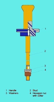
- Cool down the valve seat ring to a minimum of -25 deg C for the easy insertion of the valve seat ring. Cooling below this temperature will cause damage to the O ring.
- Insert the O ring in the valve seat ring groove with a coating of oil/Loctite before the fitment.

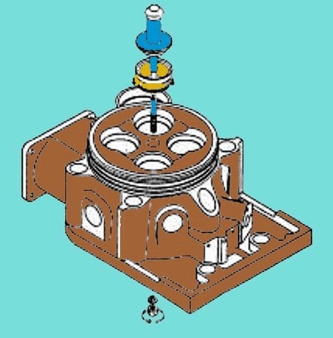
- Position the valve seat ring in the bore with the handle having stud and washer as shown in fig
- Knock at the handle and tighten the nut (4). Knock it down slowly till the seat bears against the cylinder head and a solid sound of a hammer.
- Center the valve seat ring by grinding it with a valve seat grinding machine.
Cylinder Head Mounting (Cylinder Head Marine Diesel Engines)
- Inspect the cylinder head and cylinder liner top for the cleanliness of any damage.
- Fit new O rings in the cooling water passages.
- Carry out the lubrication of the rings
- Inspect the contact surfaces of the nuts and threads for cleanliness and damages.
- Mount the cylinder head lifting tool and place the cylinder head on the top of the cylinder liner.
- Check the nuts for their easiness on the threads.
- Apply copaslip on the threads and contact surfaces.
- Put the nuts on and tight with Tommy bar.
- Tighten and loosen the new nut to relieve from their deformation
- Carry out the tappet clearance adjustment.
- Install back all the pipelines and supporting frames.
- Check the leakage test of Lube oil and cooling water.
- Fit all the covers removed before dismantling.
Cylinder Head cooling water spaces Inspection (Cylinder Head Marine Diesel Engines)
Inspect cooling water inlet and outlet as per the below fig.
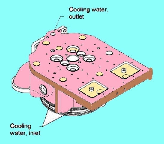
- De-scale the complete cylinder head in case of scale formation.
- Inspect the chocking by pouring the water inlet and flow out from the inlet of the cylinder head.
- Use the wire brush for cleaning purposes and carry out proper flushing.
Balancing yoke adjustment
Yoke presses the inlet valve and exhaust valves simultaneously. Balance the yoke precisely for the even and smooth operation of Valves.
Improper adjustment of clearances on yoke will cause unbalance force on the yoke, and the unbalanced yoke would cause damages on yoke and guide pin.
A broken yoke or guide will cause repeated unbalance movement of valve spindles leading to failure of valve spindles and serious damage to the engine.
Procedure for adjustment of Yoke Clearance
- Turn the crankshaft to ensure the valves in a fully closed position. The interrelated cylinder should be in the top dead center of the firing stroke.
- Check the pushrods are without spring force and free moment and clearance.
- Loosen the locking nuts (1, 3) and carry out the adjustment with adjusting screws (2, 4).
- Press the yoke on the non-adjustment side to contact valve stem (A) firmly as per the below fig.
- During the contact, (A) rotate the adjusting screw till the adjusting screw establishes the connection at valve stem B.
The easiest method is to place the dial gauge on the valve rotator and noticing the needle movement.
- Press the (A) side and measure the clearance of B by a feeler gauge.
- Similarly, press the (B) side of the yoke and adjust the clearance of ( A) by a feeler gauge.
- Keep adjusting the screw till there is no difference in clearances, in turn pressing the opposite side of the yoke.
- Repeat the adjustments till both clearances are of the same reading. On completion of the adjustment, tighten the locknut (1) holding the adjusting screw (2) for not turning while tightening. Apply the correct tightening torque and apply molycote on the nuts.
Repeating is necessary to ensure the non-tilting of the yoke on one side.
Re-confirm the clearances on completion of tightening the lock screws.
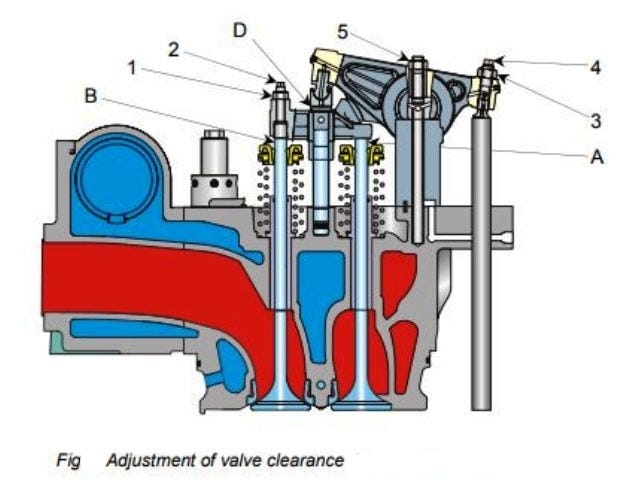
Tappet /Valve clearance adjustment
- Check and replace the wearing parts on the rocker arm assembly.
- Check the tightness of the rocker arm holding nut (5). Re-tighten the nut if found loose.
- Apply the molycote and Check the tightness with specified torque.
- Loosen the locking nut (3) and adjusting screws (4) on the rocker arm.
- Place a dial gauge on the yoke and insert a feeler gauge between the rocker arm and Yoke (D). the thickness of the feeler gauge should be as per the specified clearance.
- Turn the adjusting screw (4) till the bottom of the adjusting screw makes contact with a pushrod. Simultaneously watch the dial gauge movement.
- Tighten the locknut (3) while holding the adjusting screw arresting the turning movement, and tightening the lock nut.
- On completion of the locknut tightening, re-measure the clearance for the confirmation while pressing the pushrod side.
Conclusion (Cylinder Head Marine Diesel Engines)
I hope the post on Cylinder head for Marine Engines would have provided valuable information on cylinder heads.
I sincerely thank the readers for showing interest in this post.